21 janvier 2016
The Delta Prime Heater model, significant advantage of the Coronal Architecture.
SIMÉON Jean-Luc, President of SIMÉON Technologies, France.
Member of the Competitiveness Pole ASTech.
Member of the International Astronautical Federation (IAF).
Web site: simeontechnologies.eu
E-mail: simeon.technologies@laposte.net
SIMÉON Technologies conducts Research, Innovation (R&I) and Development in magnetic, electromagnetic, spintronic technologies for the Aerospace Industry. Our technology is based on an original and innovative electromagnetic concept named “Coronal Architecture”. The document presents recent studies conducted with the Delta Prime Heater our heating device which is a micro thermal power plant. Measurements were done with the new model in laboratory conditions in order to better understand the Coronal Architecture principle. Results confirm the advantage of this technology.
The device is a hexagon of 2 cm sides and 0.4 cm thickness. Two experiences were conducted, one in open area and another in a confined area (tube), both in ambient atmosphere (around 20°C).
The device is formed by thin layers of several inorganic materials, among which a paramagnetic material and a strategic material named “SNM-Gab” (SNM-Gab which is ionizing). Recent experiments were done in different conditions to measure the Thermal Power Deliver “P“. In this way, we used the specific heat capacity “Cp” of our strategic mineral material, the SNM-Gab-Δ1, to measure the thermal power delivered of our device, calculate in Wh/m3 and Wh/m2.
Introduction
The coronal architecture is a modularly tool with a lot of potential. Last measurements done on our new device confirm the advantage of our technology and will help to better understand some characteristics of electromagnetic devices submitted to heat. This knowledge will help the development of new processes and their improvement which represent a major area for the aerospace industry research and innovation. Additional studies on the SNM-Gab-Δ1, widespread on the moon, also confirm its efficiency, particularly concerning the thermal capacity after some improvements.
I. The Coronal Architecture presentation
The micro thermal power plant is roughly consisted of at least: a special winding design with two central orifices, two coins (paramagnetic metal), a central plate (diamagnetic metal) with a special architecture and the SNM-Gab-Δ1 material. The SNM-Gab-Δ1 is obtained from a natural material of crystalline structure with rare earths elements.
The two orifices, named Vortexes, are located only on one side of the winding architecture. Each coin is placed in one orifice of one vortex.
The Vortexes channel works as an amplifier and can be adjusted to boost magnetic fields or works as an emitter to produce charged particles. All these elements represent the key features of the Coronal Architecture.
The Coronal Architecture has a complex structure. It uses the magnetic properties of the different materials used, the quantum characteristics of the particles, including the “Spin” (i.e. electrons rotation), and the magnetic fields generated.
Using the Foucault’s systems, a high-powered current moved through the Coronal Architecture winding, creating multiple opposite electromagnetic fields concentrated inside a tiny and closed area which is the core of the device. The device is composed of several layers of material (fig. 1).
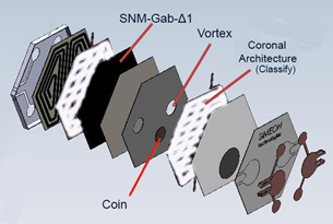
Figure 1: Presentation of the Delta Prime Heating layers
The coins are used, first, to intensify and concentrate the fields inside the core. The core then heats the surrounding materials up to a threshold which reverses the poles of other electromagnetic fields.
Once, the energy supply is switched off, it remains residual electromagnetic fields which dissipate progressively. Before the total disappearance of electromagnetic fields, the electronic control unit supplies again the device with electricity. The device can be formed with various shapes, sizes but also densities. However the technology was designed especially in precise applications, from 500 nm to 500 µm thickness, on flexible or rigid support.
II. Main characteristics of our system and material
The following measurements were done in laboratory conditions. The aim was to optimize the equilibrium between the current and the intensity submitted to the device, to optimize the energy consumption of the Delta Prime Heater. The current used is than very low. These measurements shown that our device, because of its low energy consumption, is able to use standard energy storage easily available on the market.
In our experiments, the intensity of running for this device starts at 600 mAh, until stabilization with the tension. By comparison, most energy storage unit (battery), type LR AA 1.5 volt, has intensity between 1000 to 3000 mAh.
In this context, we will compare some values concerning the Thermal Power Delivered ‘TPD” of the device submitted to different currents which are increased step by step from 1.5 volt and 0.60A until 5volt and 1.83A. In this configuration, the heating time is higher than in standard use. A figure will present these conditions of experiments: step by step heating and direct heating.
Other figure will show the performance of the coronal architecture. Two points were selected on the device with the thermocamera, X and Y. The X point represents the vortex area of the coronal architecture and the Y point represents the area without vortex.
At the end, we show measurements of thermal power delivered expressed in different units : Wh/m3 and Wh/m2.
Conditions of Delta Prime Heater measurements
Two types of measurements was done, first on ambient area another in confined area. Photo n°1 presents the experimentation conditions done with the Delta Prime Heater placed in a steel tube.
The aim was to reduce the loose of thermal energy by radiation and diffusion due to the temperature of the room (20°C).
The device was installed in a 30 cm x 8 cm x 1 mm thick steel tube, placed on a 0.6 cm thickness piece of Teflon and submitted to 5 volts and 1.83A current.
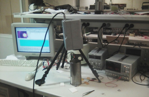
Photo 1: Delta Prime Heater temperature measurements with a thermocamera
As explained previously, the X point represents the vortex area of the coronal architecture and the Y point represents the area without vortex (photo 2).
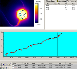
Photo 2: Difference of temperature between area X and area Y submitted to 3.5V/1.34A.
On the photo n°2, the X points (black line) represent the place of the Vortexes of the Coronal Architecture and Y (red line) the rest of surface. As shown on the figure below of the photo, the X points are warmer than Y surface. At a temperature greater than 50°C the difference between X and Y increases. When the temperature is higher than 90°C, the difference between X and Y reaches 4°C. For the following measurements we selected data only concerning the Vortex surface (i.e. the X points).
Figure 2 illustrate the thermal elevation in relation with the tension and the intensity, for each configuration from 1.5V/0.60A until 5.5V/1.96A.
Table n°1 shows data’s corresponding to the tension/intensity of current used during the experiment.
Table 1: Tension values (V) in relation to the intensity (A) of the current submitted to the device
|
V |
1.5 |
2 |
2.5 |
3 |
3.5 |
4 |
4.5 |
5 |
| A | 0.60 | 0.80 | 1 | 1.17 | 1.34 | 1.51 | 1.83 |
1.96 |
We can globally observe that temperature increase gradually, even if the time until stability at 3.5V/1.34A is longer. There is still regular increasing of the intensity, about 0.5A, for each 0.5V submitted to the device.
The red line left on figure n°2 concerned the same device measured on the tube, directly until 5volt and 1.83A (its call “5V direct”). However the configuration is the same, that’s mean in laboratory condition, were the equilibrium between tension and intensity was under control.
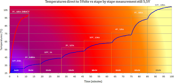
Figure 2: Increasing of the temperature in relationship with the tension and intensity submitted to the Delta Prime Heater
III. The result of measurements
The calculation of Thermal Power Delivered (TPD) was calculated using the equation Q=mc∆T in W/m3. “Q” corresponds to the thermal energy, ‘m’ the mass, ‘c’ the specific thermal capacity and ‘T’ the time.
In this photo 4), the device was placed on a piece of Teflon and in a steel tube, submitted to a 5V/1.83A direct current in order to evaluate the potential of diffusivity.
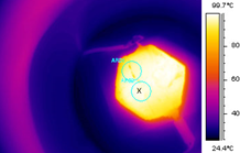
Photo 4: Specific characteristics Delta Prime Heater placed in a steel tube and submitted to 5V/1.83A direct until 99°C.
On this condition the temperature reaches fast 110°C (photos. n°5). By cooling, the ambient condition reign in this confine area reduce the loss of heat.
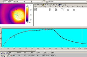
Photo 5: Delta Prime Heater placed in a steel tube and submitted to 5V/1.83A direct. Photo shows the moment of temperature decreasing and reach near 34°C.
At the beginning the 0.1cm thick inox steel tube was cold, but radiative heat transfer warm the tube borders on an important height of the tube. Photo 5 on the bottom a homogeneous distribution of heat can be observed. Other surprising reactions with the Teflon were observed, which will not be explaining here.
Figure 3 shows, upon the speed temperature increase of the device in the steel tube and under the cooling. We can see a real inertly of the delta Prime Heater confirmed by the low decrease.
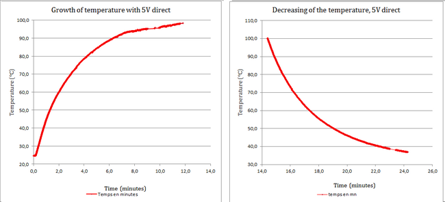
Figure 3: Temperature increasing and decreasing of the Delta Prime Heater submitted to 5V/1.83V
The ambient condition in which the device is place will influence the radiative heat around it. Data below (table n°2) shows better results than the previous experiment, with the same condition Tension and intensity. The performance is better.
Table 2: TPD of the Delta Prime Heater submitted to a direct 5V current
|
Thermal Power Delivered by the Delta Prime Heating submitted to 5V direct |
|
| Tension in Volt | 5 |
| Intensity in Ampere | 1,83 |
| TPD in W/h | 1,96*105 |
| TPD in Wh/m3 | 4,71*1010 |
| TPD in Wh/m2 | 1,88*108 |
In comparison with the previous experiments, with the device submitted to 5V/1.83A in open area and in the tube, the TPD measurements clearly shown what configuration should ensure an efficient performance.
IV. Perspective
Our products can be developed under two forms: several devices can be arranged on a flexible medium or directly on the vessel hull. Other perspectives for our devices may concern military or civil uses which needs heating technologies: Automobile, nautical activities, urban heating, clothes heating, etc.
Conclusion
The Delta Prime Heater series based on electromagnetism technologies is full of surprises and we discovered much originality. The coronal architecture and our personal approach of physics is one of our stimulus to improve new product.
The low electric consumption and the high thermal capacity of the products of SIMEON Technologies compared classical technologies based on resistance for example, can be an alternative for some needs in Automobile, Sea industry.
Acknowledgments for their technical help:
Dr. Boris GUSAROV, Dr. Eve LEROY, Dr. Orphée CUGAT


